DIY Smart CO2 Monitor Part 7: The V2 Board, Assembled by JLCPCB
At the end of Part 6 I had a custom PCB, but it was really just a carrier board for modules: an ESP32 dev board, a sensor breakout and an OLED module, all soldered on by hand. It worked, but I wanted to get rid of the soldering completely. So this time the plan was simple to say and harder to do: design a board that JLCPCB assembles for me, from bare parts, so it arrives ready to flash.
It’s finally here, and it’s the first version of this project that I’d call almost production.
What changed in V2
The sensors stay the same. The SCD41 (real NDIR CO2) and the SGP40 (VOC index) are the whole point of this project, so I didn’t touch those. Everything around them changed:
- ESP32-C3-WROOM-02 instead of an ESP32 dev board. The C3 has native USB, so there’s no USB-to-serial chip anymore. That was actually forced on me: the CH340C I had in the first draft went out of stock at JLCPCB.
- USB-C power through a TPS63802 buck-boost converter, with a PTC fuse and ESD protection on the port.
- A 1.14” IPS colour TFT (240x135, ST7789) instead of the monochrome OLED. JLCPCB solders its flex cable for a few cents per joint, so I still don’t have to touch a soldering iron.
- BOOT and RST buttons, a status LED and test pads, so I can recover a board if a firmware update ever goes really wrong.
The board is 76 x 44 mm. Every part comes from JLCPCB’s own stock, so they can place everything.
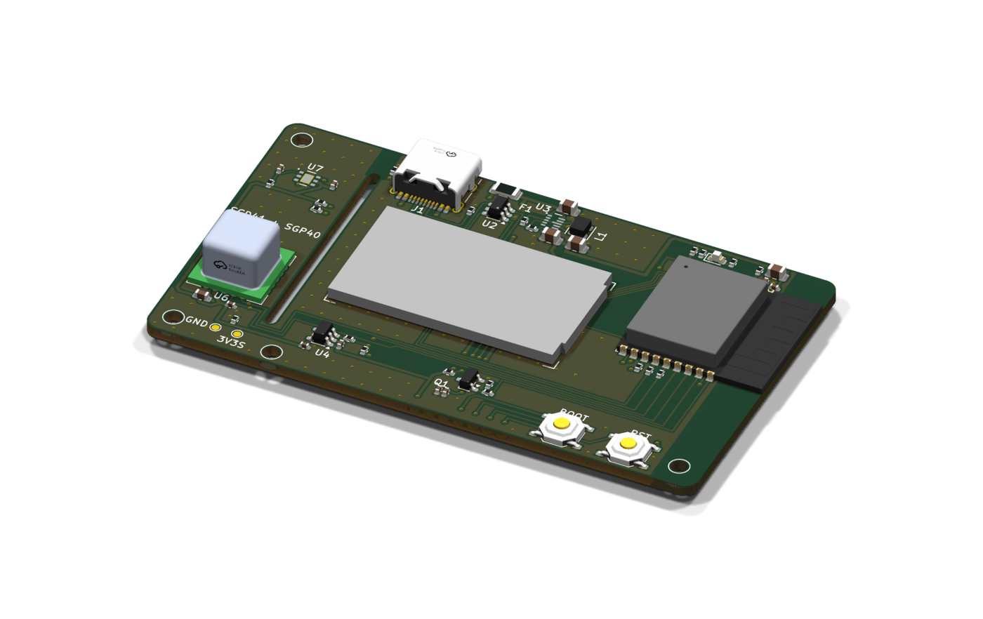
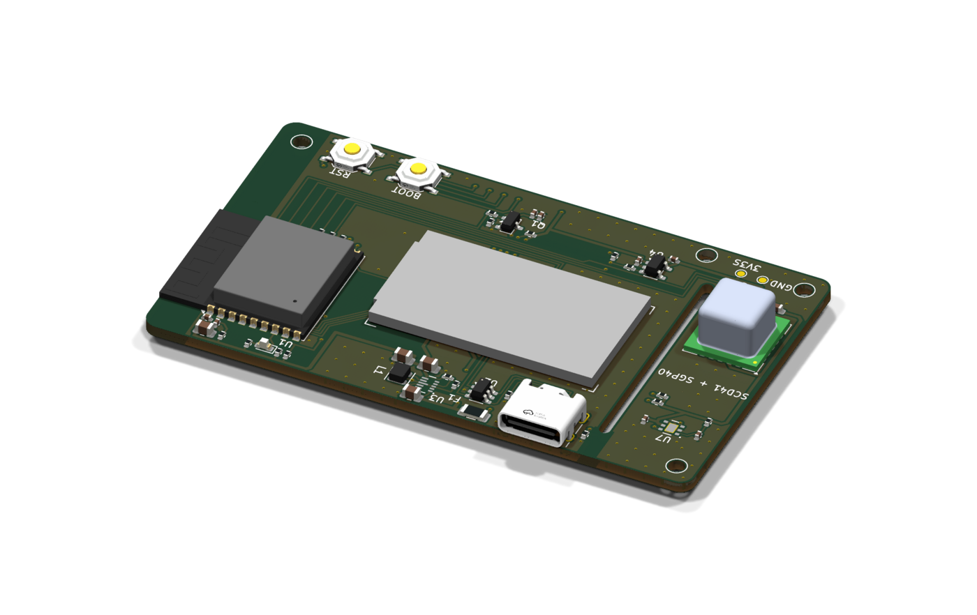
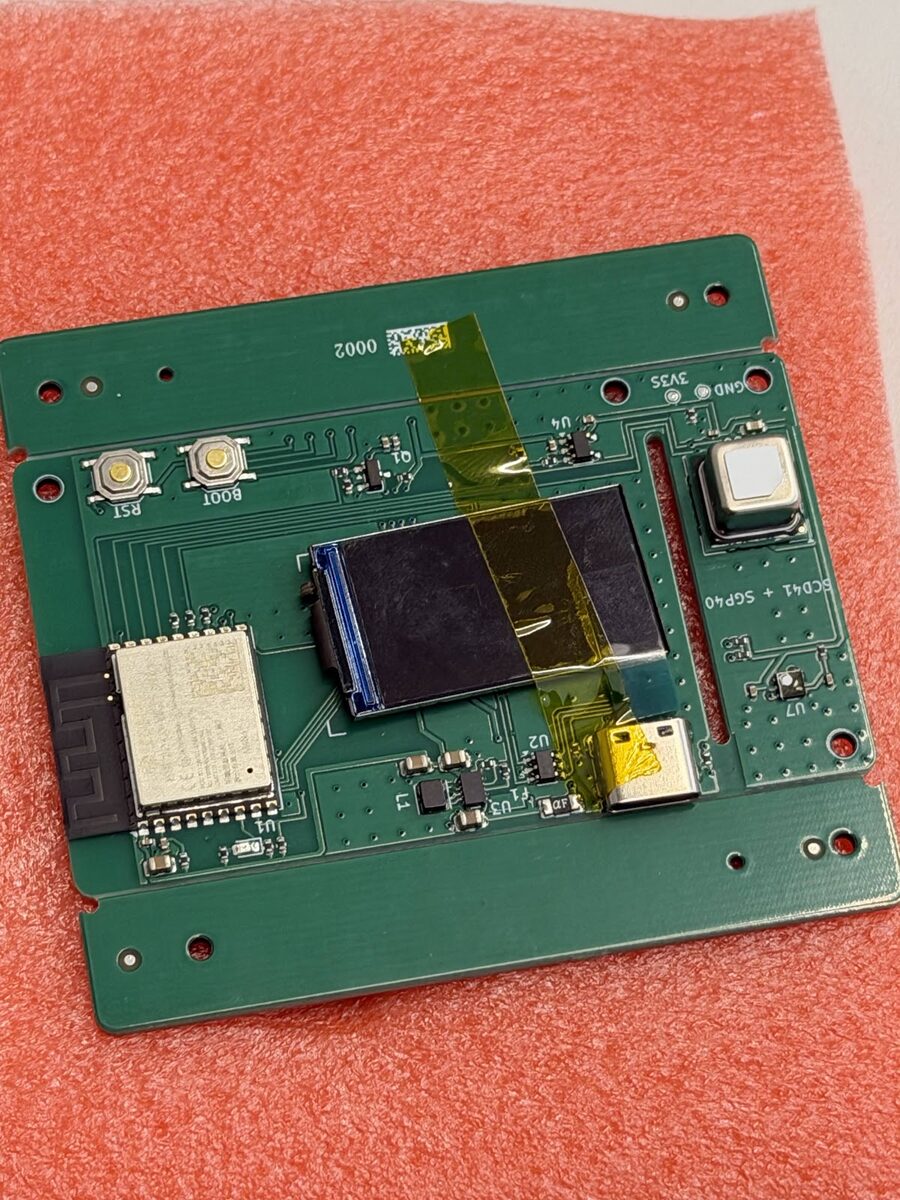
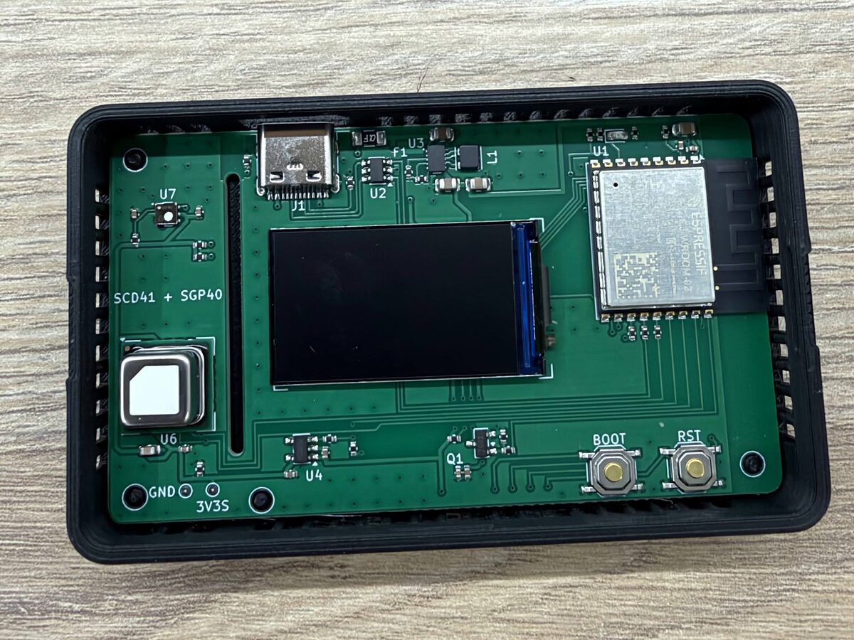
The slot next to the sensors isn’t decoration. It’s a cut in the board that keeps heat from the ESP32 and the power converter away from the SCD41, because the SCD41 also measures temperature and humidity and picks up any heat nearby.
Hardware as code
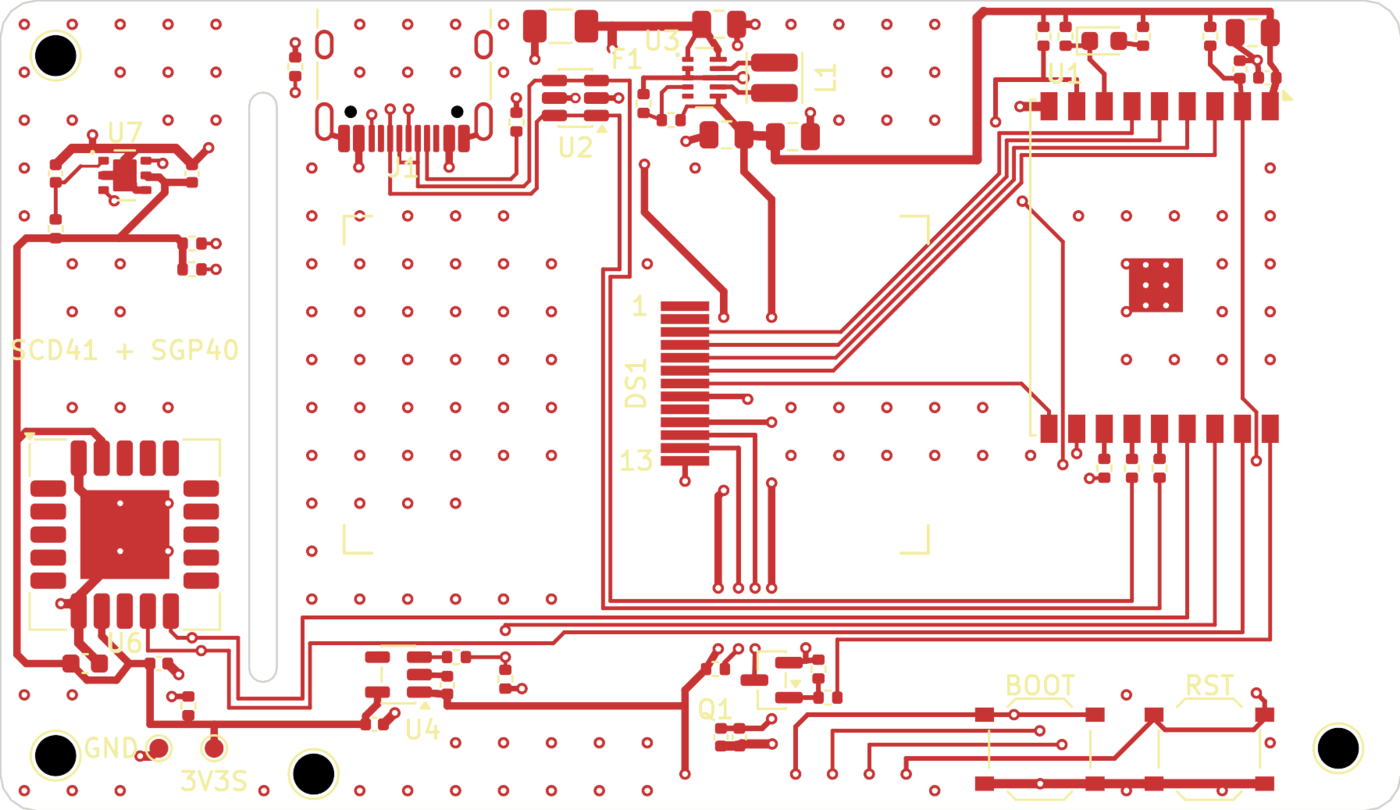
In Part 6 I drew everything by hand in EasyEDA. This time the whole board is generated from Python scripts: the schematic, the footprints, the part placement, the routing and the JLCPCB production files (Gerbers, BOM, pick-and-place) all come out of a script pipeline around KiCad 10. If I want to move a part, I change a coordinate in a Python file and re-run it, and the electrical and design rule checks run every time.
Honestly, I didn’t type most of it myself. Like the rest of this blog, this was built together with an AI agent: I described what I wanted and reviewed the results, and it wrote the generators and ran the checks. The part that surprised me was how much of the review it could do too. It caught a display flex cable footprint that would have been 2 mm off, and a soldering note that would have mirrored the display pins. Both would have meant a dead first batch.
The enclosure
The case is code as well, written with build123d (a Python CAD library) instead of OnShape. The script reads the board outline, holes, buttons and display position straight from the PCB layout, so the case follows any board change. It also runs a fit check against the 3D model of the assembled board before I print anything.
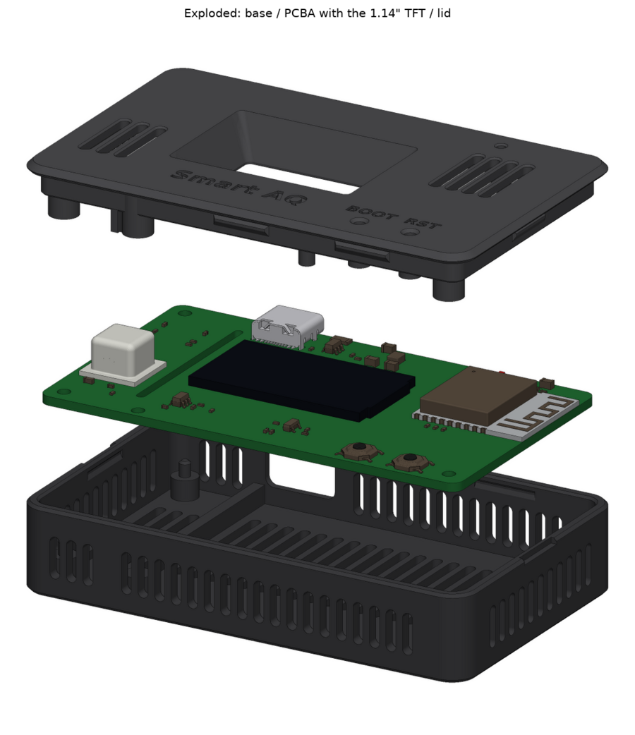
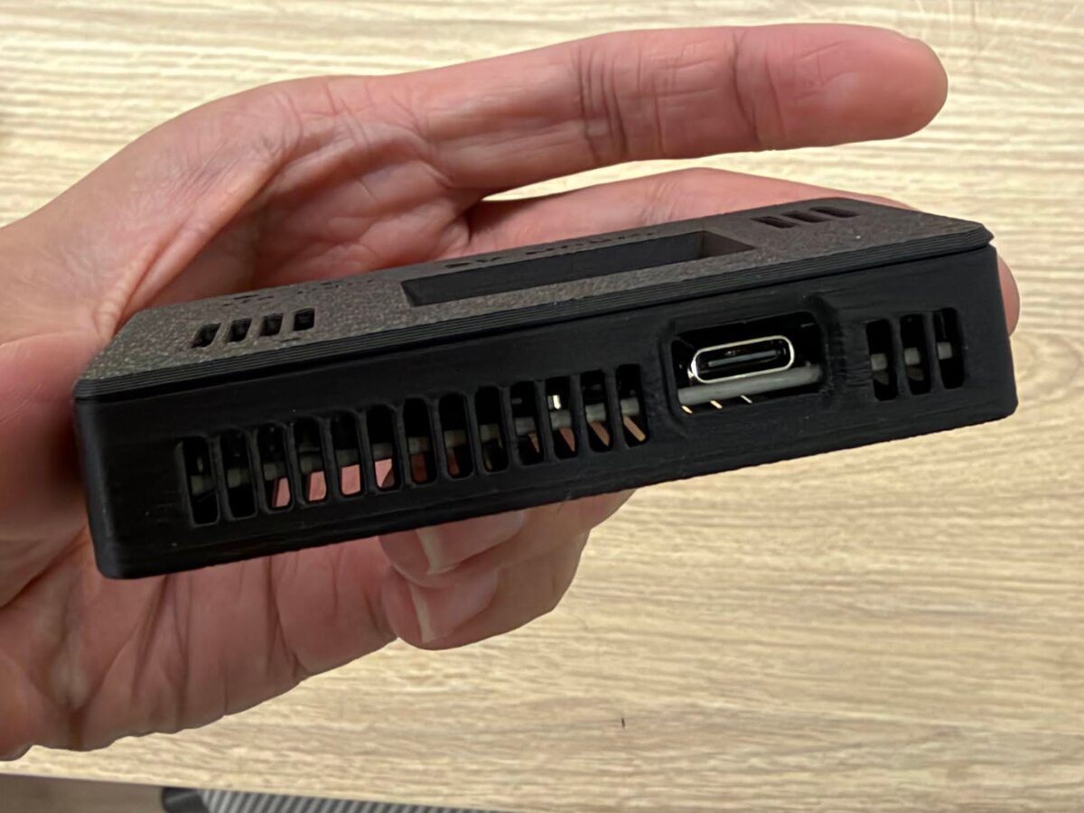
The part I’m happiest with is the sensor chamber. A wall in the lid lines up with the slot in the PCB and closes off the sensor corner, which has its own vents. Warm air from the electronics stays on the other side.
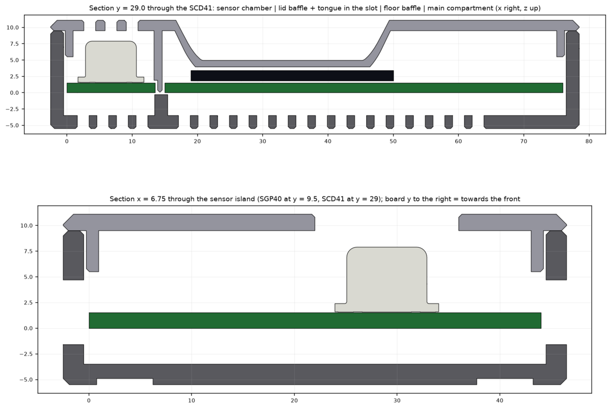
It’s a snap-fit lid, about 20 g of PLA, and it prints without supports on my A1 Mini.
Ordering from JLCPCB
PCBA is more expensive than just PCBs, mostly because of the sensors. The parts come to about USD 34 per board, and the SCD41 alone is about USD 19 of that. On top of that JLCPCB charges a setup fee, a stencil and a few dollars per “extended” part, so small orders cost noticeably more per board. Five boards come to roughly USD 44 each before shipping.
One thing I didn’t expect: JLCPCB’s engineers paused the order and emailed me because the SCD41 is marked as heat sensitive, and they wanted to check their reflow temperature with me. It’s nice that someone actually looks at the order.

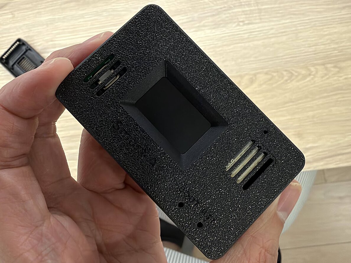
The boards came on a panel with the display already soldered. It sits folded over its flex cable, with a strip of Kapton tape so the display’s metal back can’t short the solder joints underneath.
And here it is dropped into the printed base:
New firmware
With a different chip and a colour screen, I rewrote the firmware from scratch instead of patching the old one. It’s still ESP-IDF (now v5.5), and it got a lot of things I wanted for a long time:
- A colour UI made with LVGL: the readings, a 24-hour CO2 trend, and a red “open a window” banner when the air gets bad.
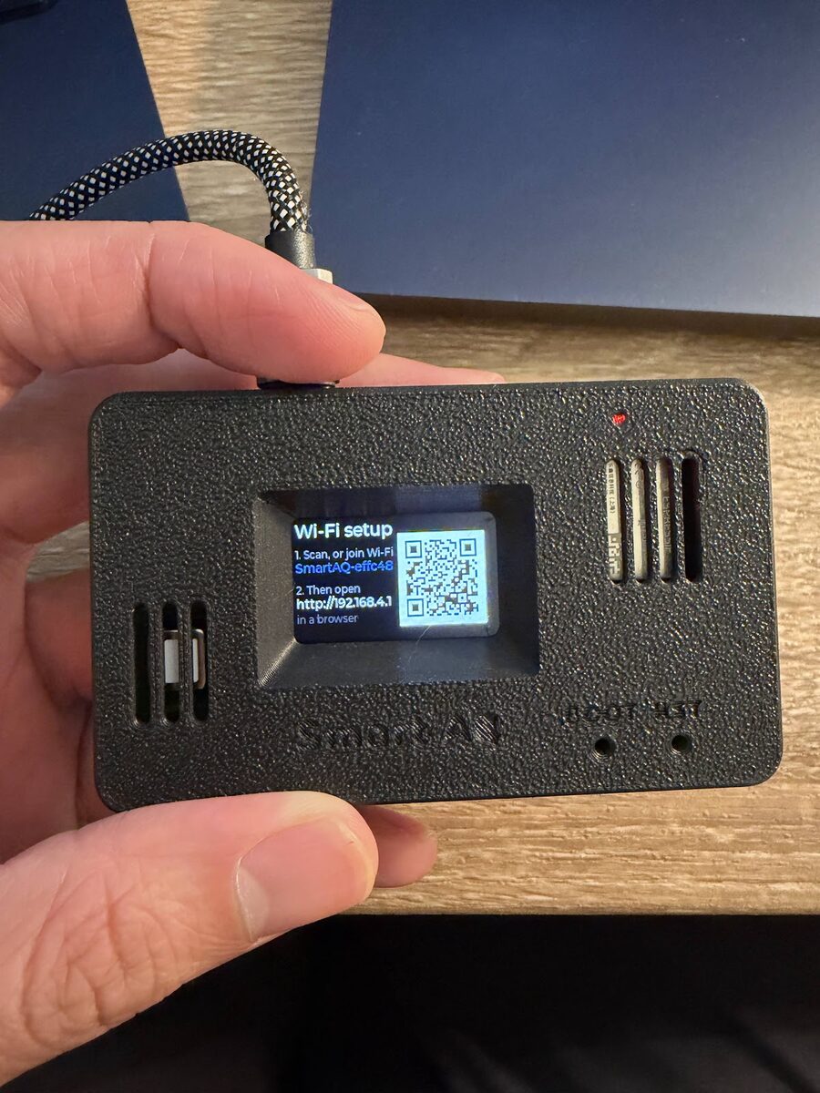
- Wi-Fi setup without hardcoded credentials. On first boot the screen shows a QR code, you join the monitor’s own Wi-Fi with your phone and pick your network.
- Updates over Wi-Fi with automatic rollback: if a new firmware doesn’t come up properly, the board goes back to the previous one by itself.
- A small web dashboard on the device, a Prometheus
/metricsendpoint, and MQTT with Home Assistant discovery. - The last 24 hours of readings stored in flash, so a reboot doesn’t wipe the chart.

I also made a single command line tool for my Mac, ./aq, so I don’t have to remember any ESP-IDF commands. ./aq setup installs the toolchain, ./aq flash flashes over USB-C, ./aq provision sets up Wi-Fi, and after that ./aq ota pushes updates over Wi-Fi. Because the boards weren’t here yet while I was writing it, most of the firmware was developed in QEMU with simulated sensors first, so it mostly just worked when the real boards arrived.
First boot, asking for Wi-Fi:
In real life
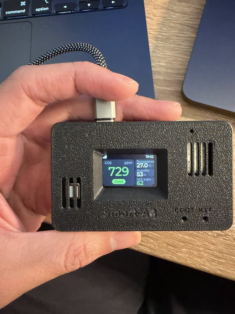
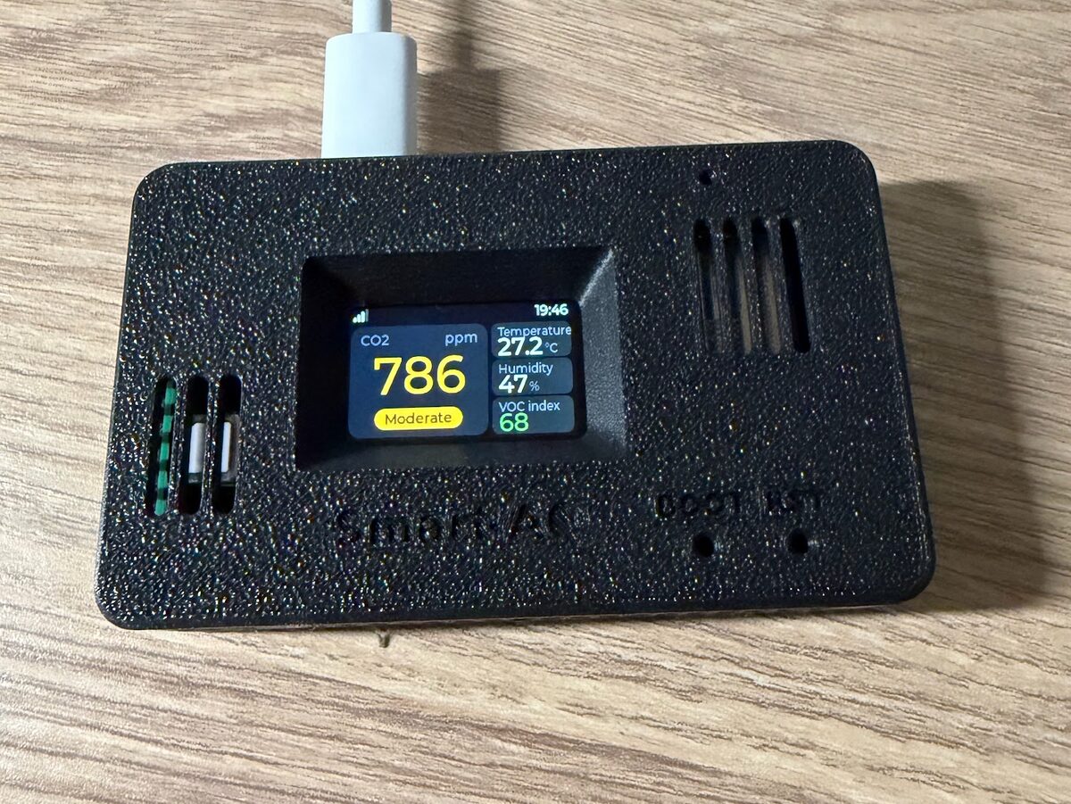
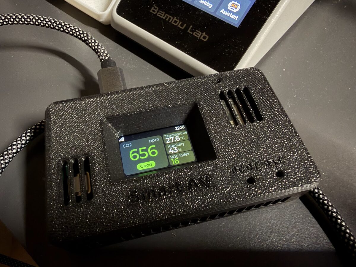
The 786 ppm on my desk and “Moderate” next to it is pretty normal for a closed room with one person working in it. It goes back to green quickly once I open the window.
Grafana on the NAS
The Prometheus and Grafana setup from Part 3 was a hand-written config with one hardcoded IP address. I replaced it with a proper stack that lives in the same repo as the firmware and hardware, and runs on my Synology NAS in Docker. New monitors announce themselves over mDNS, so they show up in Grafana by themselves; I only give them a room name. The dashboards are generated from a script too, and Grafana can alert me if a monitor goes offline or the CO2 stays bad for too long.
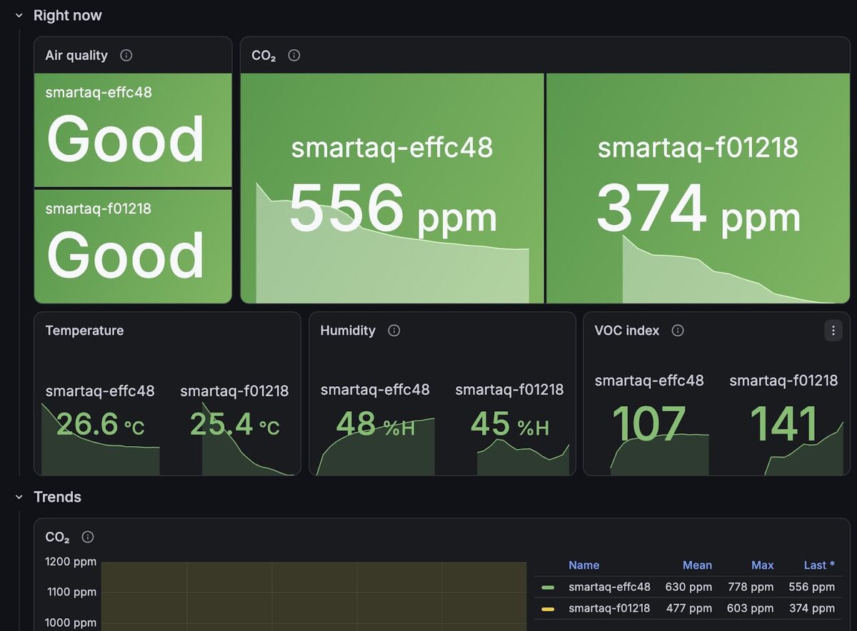
Two monitors are running now. I haven’t even given them room names yet, which is why they still show up as smartaq-effc48 and smartaq-f01218.
What’s next
The goals from Part 1 are basically done, and this is the first version where I’m not embarrassed to put one in every room. Next I want to:
- Add a battery. Right now it always needs a USB-C cable, which decides where it can sit. With a rechargeable battery and a charger on the board, I could carry it from room to room, or put it on a shelf without a cable hanging down. The tricky part is the SCD41: it isn’t a low-power sensor, so I’ll need to think about the measurement interval, sleeping the screen and Wi-Fi, and how big the battery and case have to get.
- Leave them running for a few weeks and compare the temperature readings against a reference thermometer, to tune the self-heating offset of the case.
- Build a few more for the rest of the house.
- Clean up the repo and publish the hardware files, so anyone can order the same board from JLCPCB.